Wisconsin Parts Database Instructions and Discussion Team/Group > OTHER STATES
> Industrial Parts
> Add
> Fluke pm 2813 programmable power supply PM2813
Fluke pm 2813 programmable power supply PM2813
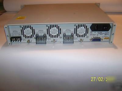
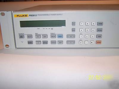
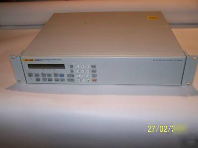
What we have here is A Fluke PM 2813 / 01n programmable power supply, Below is some information from there web page, any other questions please feel free to ask.
Fluke now offers two types of power modules:
* Autoranging power modules for superior voltage and current versatility. The PM 2811, PM 2812 and PM 2813 offer autoranging in 60W and 120W, up to 180W per mainframe.
* Linear power modules with superior response time and noise performance. The PM 2830 family offers linear power modules from 120W, up to 240W per mainframe.
The PM 2800 series are built around a choice of five output power modules:
* 60V, 10A, 120W autoranging
Because of their modularity, these power supplies are available in a number of configurations, including single-, dual- and triple-output versions with various combinations of power modules. In multiple output models, each output is independently programmable and isolated from other outputs. In total there are 16 models to choose from.
Reliability of power supplies is of extreme importance. The PM 2800 family of programmable power supplies, with their extensive internal self-monitoring device protection features and generous cooling, are designed for years of trouble-free service.
Front panel operation is easy. Just set up the desired voltage, current and protection levels, and press the Operate/Standby key to enable the power at the output terminals. Each front-panel key has only a single function, with the exception of the auxiliary (AUX) key which is used for system information such as GPIB address, display intensity, calibration mode etc.
Each model is equipped with a GPIB/IEEE-488.2 interface which supports the Standard Commands for Programmable Instruments (SCPI).
SCPI provides a common command set across a wide range of test and measurement instruments. By conforming to this industry standard in programming, the task of creating and supporting GPIB application programs is made easier.
An extensive set of protection features had been included to protect your load or Device Under Test. Voltage and current are constantly monitored by a separate readback circuit. This readback circuit has its own sense lines to compensate for voltage drops in the power distribution lines. The load is protected in case of an open sense line.
Pressing the Operate/Standby key removes all power from the putputs immediately. The voltage and current values can be set up in standby mode before applying power to the Device Under Test.
Over-Voltage Protection (OVP) and Over-Current Protection (OCP) are both user-programmable. When a voltage or current limit is reached, power is removed from the outputs instantly.
The power supply's internal temperature is continuously monitored. If the temperature rises excessively, over-temperature protection shuts down the output power fast.
The protection mode has a programmable delay that allows it to ignore short-term overloads such as power-up current surges for intervals of up to 60 seconds.
For dual- and triple-output power models, the Clupled Protection mode ensures that all outputs shut down simultaneously when a fault is detected in one output. This is an important feature for applications requiring positive and negative balanced voltages such as an operational amplifier.
When a fault such as Over-Voltage or Over-Current occurs, the power supply can generate a GPIB service request (SRQ). The faults that generate the interrupt are user-selectable by setting SRQ mask bits either remotely or from the front panel. Fault conditions are clearly displayed on the front panel.
Voltage source or current source
The power supply can act either as voltage source or as current source, depending on the load conditions and the selected values of Vset (voltage setting) and lset (current setting).
Up to 99 settings per output can be stored and recalled from the internal memory of the power supply. The voltage and current settings of all outputs are stored in a non-volatile memory with battery backup. The last instrument settings are automatically stored on power-down.
The power supplies are equipped with external trigger lines which can be used to recall voltage and current settings from the internal memory. This allows accurate synchronization with other equipment and results in less GPIB bus traffic.
The STEP function allows the voltage and current settings stored in the internal memory to be recalled successively, and to be activated if the supply is in Operate mode, by pressing a single key.
The following setting is recalled and activated each time the STEP key is pressed. This function allows the user to create test patterns (complete with repetitive loops).
Test patterns can be executed automatically using the AUTOSTEP mode, without the need for a PC. The time between two successive recalls can be defined by the user (min. 0.01s, max. 60s).
The power supplies can be set up to deliver maximum power to your load by automatically adjusting the voltage and current settings. For example, a resistive load is connected to your power supply with 6V and 10A, a total of 60W power. If the voltage were increased to 7V, the current would have to be readjusted manually to 8.6A to continue getting 60W delivered to your load in normal mode. Using coupled parameters mode, the current setting is adjusted automatically to 8.6A by the power supply to get the full 60W.
Each power supply has a 16-character front-panel display with a 5 x 7 dot character matrix, using super twisted LCD technology. The display allows presentation of alphanumeric data and is backlit for easy readout.
The power supply does not need to be removed from a rack or system for calibration. All you need is a calibrated multimeter. Access to the power supply calibration mode is protected with a user-programmable password.
The PM 2800 family of Programmable Power Supplies offers convenient, single-box solutions for a wide range of applications.
The PM 2810 family is designed for situations where high currents (up to 10A per output) or a wide voltage and current adjustment range are required. These models are available in single-, dual- and triple-output versions, with a maximum of 180W (3 x 60W or 60W + 120W) per mainframe.
The PM 2830 family offers solutions for applications requiring higher voltages (up to 120V DC), for the testing of sensitive analog printed circuitry, or for situations in which not only a sourcing supply is needed, but also the ability to sink current (e.g. to simulate battery leakage) is required. This family is available in single- and dual-output versions, with a maximum of 240W (2 x 120W) per mainframe.
All models can also easily be used for stand-alone benchtop operation. Optional front-panel connectors can be specified for this purpose.