Wisconsin Parts Database Instructions and Discussion Team/Group > ILLINOIS
> Motors and tools
> Dc motor wireless controller (climb and descent)
Dc motor wireless controller (climb and descent)
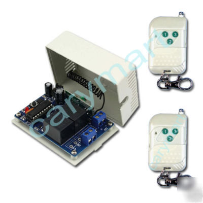
DC Motor Wireless Controller (Climb and Descent)
DC Motor RF Remote Control Transmitter & Receiver
* 1 X Receiver: S1FU-DC12 (Inversion Control Mode / DC12V)
* Wireless control, easy to install.
* Control motors of Fan, Pump, Electrically operated Winches/ Doors / Windows / Blinds or Other Appliances with voltage DC 12V.
* You can turn on/off the receiver with transmitter (remote control) from any place within a reliable distance, the wireless signal can pass through walls, floors and doors.
* Reliable control: The transmitter (Encoding) and the receiver (Decoding) use an 8-bit code.
* One/several transmitters can control one/several receivers simultaneously.
* If you use two or more receivers in the same place, you can set them with different codes.
* Transmitting Frequency: 315MHz / 433MHz
* Control Modes: Inversion (Toggle, Momentary, Latched)
* Power Supply (Operating Voltage): DC 12V
* Working Voltage Range of Relay: DC 12V
* PCB size: 68mm x 48mm x 20mm
* Case size: 75mm x 55mm x 30mm
* Remote Control Distance: 100m / 300ft (theoretically)
* Encode: Fixed code by Soldering
* Unit size: 58mm x 39mm x 16mm
* Power Supply: 1 x 23A -12V battery (included, can be used for 12 months)
1) Setting control mode Toggle: Connect Jumper-1 and Jumper-2. Control mode Toggle: Press -> On; Press again -> Off.
Press button C: Terminals 1 and 2 are the output of DC 12V (1: , 2: ), motor rotates in the positive direction.
Press button C again: Terminals 1 and 2 no output, motor stops
Press button B: Terminals 1 and 2 are the output of DC 12V (1: , 2: ), motor rotates in the reversal direction.
Press button B again: Terminals 1 and 2 no output, motor stops
2) Setting control mode Momentary: Only connect Jumper-1. Control mode Momentary: Press and hold -> On; Release -> Off.
Press button C and hold: Terminals 1 and 2 are the output of DC 12V (1: , 2: ), motor rotates in the positive direction.
Release button C: Terminals 1 and 2 no output, motor stops
Press button B and hold: Terminals 1 and 2 are the output of DC 12V (1: , 2: ), motor rotates in the reversal direction.
Release button B: Terminals 1 and 2 no output, motor stops
3) Setting control mode Latched: Do not connect Jumper-1 and Jumper-2. Control mode Latched: Press -> On; Press another button -> Off.
Press button A: Terminals 1 and 2 no output, motor stops.
* The receivers with other power supply: S1FU-DC09 (9VDC), S1FU-DC24 (24VDC).
E-mail to us - ****@carymart.com if you have any more questions.