Wisconsin Parts Database Instructions and Discussion Team/Group > ILLINOIS
> Electrical Components
> Add
> Used
> Honeywell 32001676-001 humidifier circuit board
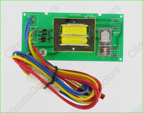
Honeywell 32001676-001 humidifier circuit board
Honeywell 32001676-001 Humidifier Circuit Board
PCB controls fan and solenoid and provides 24 vac for (automatic) humidistat.
Inspect the mylar wrap on the windings for discoloration or melting (from over heating). Inspect the diodes and traces for burn-outs.
To test this board we apply 120 vac to the terminals labeled LINE VOLTAGE. The humidistat (connects to E5-E6) is simply a switch that opens and closes. Thus to test, touch the yellow wires that connect to E5-E6 together. You should then hear the relay click. The solenoid and fan would then get power.
The diodes rectify the voltage to DC that is used to drive the on-board relay. Connecting the yellow wires (E5-E6) together routes the 24 vac to dioides, producing the DC voltage that closes the relay contacts. If the diodes or relay have failed, then the 24 vac at E3-E4 would be present when the yellow wires are unconnected. But the relay would not click closed when the yellow wires are connected.
The blue wires connect to E3-E4 and provide 24 vac for the H1008A1008. When using the manual humidistat H8908B1010, the blue wires are unused. They should not be left to dangle where they could short together. Shorthing the blue wires togther can burn-out the on-board transformer.
This board is working if fan runs when:
1. Place cover fan assembly on bench.
2. Yellow wires are jumped (see photo below).
3. 120v cord is plugged in (caution running fan without guard).