Wisconsin Parts Database Instructions and Discussion Team/Group > WISCONSIN
> Industrial Parts
> Add
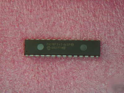
> Pic 18F242 PIC18F242 i/sp 10 mips 16K 10-bit ad dil 28
Pic 18F242 PIC18F242 i/sp 10 mips 16K 10-bit ad dil 28
C compiler optimized architecture/instruction set
- Source code compatible with the PIC16 and PIC17 instruction sets
Linear program memory addressing to 32 Kbytes
Linear data memory addressing to 1.5 Kbytes
- DC - 40 MHz osc./clock input
- 4 MHz - 10 MHz osc./clock input with PLL active
16-bit wide instructions, 8-bit wide data path
8 x 8 Single Cycle Hardware Multiplier
High current sink/source 25 mA/25 mA
Three external interrupt pins
Timer0 module: 8-bit/16-bit timer/counter with 8-bit programmable prescaler
Timer1 module: 16-bit timer/counter
Timer2 module: 8-bit timer/counter with 8-bit period register (time-base for PWM)
Timer3 module: 16-bit timer/counter
Secondary oscillator clock option - Timer1/Timer3
Two Capture/Compare/PWM (CCP) modules.
CCP pins that can be configured as:
- Capture input: capture is 16-bit, max. resolution 6.25 ns (TCY/16)
- Compare is 16-bit, max. resolution 100 ns (TCY)
- PWM output: PWM resolution is 1- to 10-bit, max. PWM freq. @: 8-bit resolution = 156 kHz 10-bit resolution = 39 kHz
Master Synchronous Serial Port (MSSP) module,
- 3-wire SPI (supports all 4 SPI modes)
Peripheral Features (Continued):
Parallel Slave Port (PSP) module
Compatible 10-bit Analog-to-Digital Converter module (A/D) with:
Programmable Low Voltage Detection (PLVD)
- Supports interrupt on-Low Voltage Detection
Programmable Brown-out Reset (BOR)
1,000,000 erase/write cycle Data EEPROM memory
Selectable oscillator options including:
- 4X Phase Lock Loop (of primary oscillator)
- Secondary Oscillator (32 kHz) clock input
Single supply 5V In-Circuit Serial Programming (ICSP ) via two pins
Low power, high speed FLASH/EEPROM technology
- < 0.2 A typical standby current