Wisconsin Parts Database Instructions and Discussion Team/Group > MICHIGAN
> Motors and tools
> Remove
> Used
> Without Warranty
> I2C lcd display driver chip
I2C lcd display driver chip
I2C - Serial LCD controller Chip
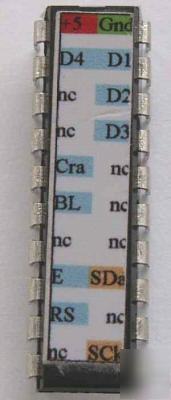
This is a purpose programmed IC to enable interfacing of a standard 1,2 and 4 line LCD display to an I2C interface. The chip has a label on top for easy wiring. The diagram below shows the minimal interface that is required. In this instance no additional components are needed.
There is a contrast output, this is either high (which turns off the display ) or low which gives the display full contrast. A trimmer potentiometer can be used for varying the contrast. There is also a back light output which is either high or low and can be wired to the anode or cathode of the displays back light LED.
The IC is a 20 pin DIL, unused pins should be left unconnected.
This is the minimal wiring diagram that will give maximum contrast. The I2C bus requires two pull up resistors.
This is the full circuit diagram showing how to arrange the contrast and pull up resistors for the I2C interface. The contrast can be connected directly to the contrast pin on the chip. this will give the maximum contrast.
The display is controlled by a simple command set and is sent to the I2C bus in a consistent way. It has an initial device address of 0x42 but this can be changed in software.
There are just 6 LCD commands and 6 system commands that enable controlling all aspects of the attached display. All commands begin with a start address followed by the command number.
( this is for writing )
(this is for reading)
Command 1 Sends a command to the LCD display, to clear the screen change the cursor etc.
Command 2 Sends data to the LCD display, this is for displaying characters
Command 3 Turns on / off the back light
Command 4 Prints a message stored in EEPROM
Command 5 Controls the contrast line to blank the display (note this is either on or off)
Command 6 Locates message area
There is a sign on message when the display is first powered on, this is stored in EEPROM and can be changed by using one of the system commands. The system commands enable reading and writing to the EEPROM and changing the device address. The address can be temporarily or permanently changed. There is also a hardware reset sequence to reset the factory defaults.
The I2C commands are buffered in an internal 32 character buffer and are not acted upon until the stop command is recieved.
This is the display chip wired to a 4 line x 20 character display. The four wires going off are the power, +5V, GND and SDA SCL lines.
* Simple command set for direct interface to LCD module
* Contrast pin allows display blanking
* 31 character buffer for I2C
* Operating voltage 2.0 to 5.5V