Wisconsin Parts Database Instructions and Discussion Team/Group > INDIANA
> Machine Parts
> Replace
> Bdt quikstor 162
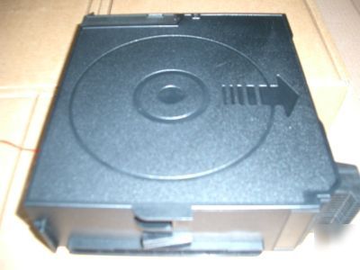
Bdt quikstor 162
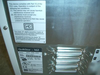
I have a brand new Quikstor 162 manufactured by BDT.
Part number for this item is 950 468 293.
This unit is a great for office use or person with lots of data to store.
It takes both CDs and DVDs exchange time between cartridge is about 5 second each.
This Operator s Manual contains information that will help you set up and
use the QuikStor 72 & 162. You do not need any specialized computer
knowledge to operate the QuikStor 72 & 162.
About this manual The QuikStor 72 & 162 accepts both CD-ROM (Read-Only Memory)
and CD-R (Recordable) Drives. In this manual they are referred to
collectively as drives unless there is a need to differentiate between
Product description The QuikStor 72 & 162 can store up to 72 CDs in 4 magazines or 162
in 9 magazines, each containing 18 discs each. You may install up to
two CD-ROM or CD-R drives, in any combination. See the section in
this chapter entitled, Configuring your QuikStor 72 & 162 .
Drives and magazines fit interchangeably in the storage bays. However,
drives may only be installed in the bottom two storage bays, starting at
You may use any 120 mm CD-ROM or CD-R media. For optimum
performance and data retention when recording to CDs, CD-Writable
CDs can be bulk-loaded in magazines or individually loaded through the
The QuikStor 72 & 162 is developed, manufactured, and serviced by
The QuikStor 72 & 162 robotics and drives are controlled over a singleended
Small Computer System Interface (SCSI-2).
921-156-401-00 August 2000 Page - 11
The following figure illustrates the configuration options for the
installed. You may purchase additional drives at any time and install
them yourself. For instructions on how to install drives, see Chapter 8
Magazines are packed separately from the QuikStor 72 & 162 and must
may purchase and install additional magazines at any time.
CD media is not included with the QuikStor 72 & 162 . It must be
Configuration options QuikStor 72
QuikStor 162 can have one drive with 162 CD s
921-156-401-00 August 2000 Page - 12
921-156-401-00 August 2000 Page - 13
This chapter contains technical information about the QuikStor 72 & 162.
Specifications Physical Characteristics
Weight, including magazines and
Technical Specifications (QS 72/QS162)
Maximum disc storage 72 CDs / 162 CD s
Maximum data storage (650 MB/disc) 46.8 GB / 105GB
Maximum magazine installation 4 / 9
921-156-401-00 August 2000 Page - 14
specifications Disc Exchange Time
The QuikStor 72 & 162 Disc Exchange Time is defined as the time
necessary for the robotics to:
pick a disc from a drive (robotics located at the drive, drive drawer
move to a magazine and load the disc into the magazine tray.
QuikStor 72 & 162 Disc Exchange Times
Mailbox - Individual load 15 sec./disc
Magazine - 18 discs/magazine 30 sec./magazine
Mean Time Between Failure (MTBF)
Mean Exchanges Between Failures (MEBF)
921-156-401-00 August 2000 Page - 15
921-156-401-00 August 2000 Page - 16
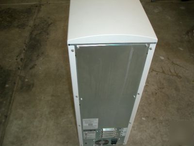
Power cables The power connector on the rear panel of the QuikStor 72 & 162
complies with IEC 320. The connector on the library end of the power
cable must comply with (IEC) EN 60 320/ C13.
Depending on your location, the following power cable is provided with
921-156-401-00 August 2000 Page - 17
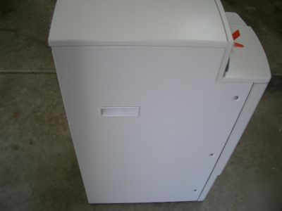
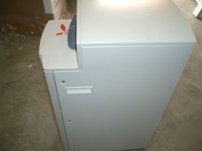
Exterior This chapter describes the operating features of the QuikStor .
Exterior features of the QuikStor 72 & 162
1. Indicator lights 5. Front door with lock
3. Open/close button, mailbox 7. Power switch
921-156-401-00 August 2000 Page - 18
Indicator lights - there are three indicator lights on the front of the
QuikStor 72 & 162. See the section entitled, indicator light status in
Chapter 9, for an explanation of the lights. From left to right they are:
Mailbox - The mailbox is used for loading and unloading individual CDs.
CAUTION: Do NOT use the mailbox drawer to lift or move the
QuikStor 72 & 162! Doing so can damage the drawer and
Open/Close Button, Mailbox - press this button to open or close the
Handles - the handles are used for lifting or moving the QuikStor 72 &
921-156-401-00 August 2000 Page - 19
Front door with lock - the front door is unlocked and opened with the
key provided. The front door allows access to the interior of the QuikStor
72 & 162. You need to unlock and open the front door to install or
remove magazines and drives, and to set or change SCSI IDs.
The front door lock can be controlled via the host computer. If the hostcontrolled
lock is enabled, access through the front door is not possible
when the unit is powered on, even with a key. If the host-controlled lock
is disabled, access through the front door is as described above. The
default for the host-controlled door lock is disabled. Consult your CD
server software documentation for more information.
When the front door is opened, an interlock switch disables the robotics
after the QuikStor 72 & 162 completes any tray or drawer operation in
progress. Drive operations are not disabled.
Front Door Key - two identical keys are provided with the QuikStor 72 &
162. If you require a replacement key, contact your reseller.
SCSI Connectors - the two SCSI connectors, labeled A and B, provide
SCSI connections to the QuikStor 72 & 162 from the host computer.
Power switch - the power switch turns the QuikStor 72 & 162 on and off.
Power connector - the power connector provides AC inlet power to the
921-156-401-00 August 2000 Page - 20
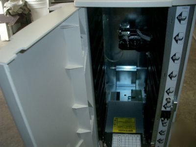
Interior features of the QuikStor 72 & 162
1. SCSI ID switch for drives 5.SCSI harnesses
2. EMI shields 6.Power harness
3. Drive/magazine bays 7. SCSI ID switch for robotics
SCSI ID switches - there is a SCSI ID switch for each of the installed
drives and one for the QuikStor 72 & 162 robotics. Each device on a
SCSI bus must be assigned a unique SCSI ID.
All SCSI ID switches are identical and each has two push buttons. To
increase the SCSI ID number, press the bottom button. To decrease the
SCSI ID number, press the top button.
921-156-401-00 August 2000 Page - 21
EMI shields - the library robotics and each drive is provided with an
ElectroMagnetic Interference (EMI) shield. The EMI shields control
electromagnetic transmissions or emissions that could interfere with the
operation of the drives or the QuikStor 72 & 162.
There are three styles of EMI shields:
A-Style EMI shield - installed on the top or last drive in the QuikStor
B-Style EMI shield - installed on all drives except the top one and
C-Style EMI shield - installed over the library robotics and
921-156-401-00 August 2000 Page - 22
Drive/Magazine bays - there are five Drive/Magazine bays. Each bay is
identified with one of three labels that indicates what may be installed in
that bay, as illustrated below: On QS 162 model magazine or drive can
be in bays 2-4 and magazines only in bays 5-10 .
Configuration label - the configuration label is affixed to the A-style EMI
shield and indicates how the SCSI devices in the QuikStor 72 & 162 are
configured. This label should be updated if drives are added or if the
SCSI configuration changes. See the section entitled, Filling out the
configuration label in Chapter 7 for instructions on filling out the label.
SCSI harnesses - the QuikStor 72 & 162 supplies two pre-installed SCSI
harnesses for connecting the library robotics and drives. See the section
entitled SCSI harnesses in Chapter 7 for details on the SCSI
Drive power harness - the power harness has two power connectors,
SCSI ID harness - harness used to communicate the drive position and
SCSI ID to the robotics control board.
921-156-401-00 August 2000 Page - 23
QuikStor CD Library 18-Slot Magazines enable you to bulk-load CDs into
the QuikStor 72 & 162. Each magazine contains 18 slide-out trays. Each
tray holds one CD. You may purchase additional CD Library 18-Slot
Magazines at any time. Contact your sales representative.
You can manually load CDs into the magazine trays before you install
the magazine in the QuikStor 72 & 162. Or, empty magazines can be
installed in the QuikStor 72 & 162. If empty magazines are installed, the
CDs must be loaded individually through the mailbox and put into the
magazine trays, or a drive drawer, through a command from the host
This chapter describes how to:
apply bar code labels to magazines
manually load CDs into the magazine trays
install a magazine in the QuikStor 72 or 162
921-156-401-00 August 2000 Page - 24
162. They are provided in sheets of six sets of labels per sheet (two
labels per set), and are packed with the manuals and other labels. To
order additional bar code labels, contact your reseller.
Apply the bar code labels to the magazine before you install it in the
QuikStor 72 & 162. The bar code labels allow the QuikStor 72 & 162 to
identify the magazine during the inventory process.
To apply the bar code labels, peel the labels from the sheet and apply to
the magazine in the locations noted below. Be sure to apply the labels in
the same orientation as illustrated.
921-156-401-00 August 2000 Page - 25
To manually load CDs in the magazine trays:
1. Press the plastic spring on the side of the magazine to unlock the
trays, and slide a tray out just far enough to clear the disc area.
NOTE: Do not pull the tray completely out of the magazine. If this
happens, the tray must be replaced in its original orientation
Loading a CD in the Magazine Tray
2. Place a CD, label side up, in the tray. Make sure the CD sits flat in
3. Press the spring and slide the tray and CD all the way into the
921-156-401-00 August 2000 Page - 26
You can add magazines to the QuikStor 72 & 162 or change the
position of existing magazines at any time. No tools are necessary for
1. Unlock and open the QuikStor 72 & 162 front door.
2. Determine which bay you wish to use for the magazine. The label on
the right side of each bay indicates whether a drive, a magazine, or
3. Make sure the arrow on the top of the magazine is pointing into the
library. Firmly, but carefully, slide the magazine into the bay slot until
CAUTION: Do not use force to push the magazine into the bay slot.
Damage to the magazine or your media could result.
4. Close and lock the QuikStor 72 & 162 front door.
921-156-401-00 August 2000 Page - 27
Removing magazines To remove a magazine from the QuikStor 72 & 162, grasp the
magazine by the finger hole and pull with a firm, steady pressure.
You may install or remove magazines while the QuikStor 72 & 162 is
powered up. When you close the front door after installing or removing
magazines, the library performs a partial automatic inventory. The
inventory records the absence or presence of a CD in the magazines
that were changed or added while the door was open. The inventory
will take about 30 seconds per changed magazine.
NOTE: Opening the front door and changing magazines does not affect
drive operations. Any current reading or writing processes will
continue while the door is open.
921-156-401-00 August 2000 Page - 28
5 Setting up the QuikStor 72 or 162
Follow the instructions in this chapter to prepare the QuikStor 72 or 162
for operation. The only tool you need for these activities is a flat blade
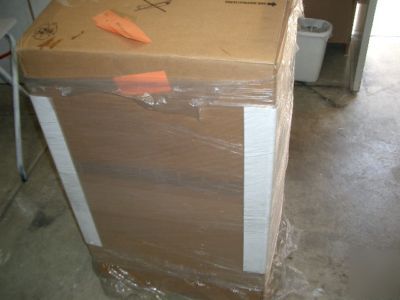
Packaging contents The packaging carton contains the following items:
Clear plastic bag containing:
Power cable (except in Asia/Pacific Region and Greater China)
External SCSI terminator connector (male)
QuikStor 72 or 162 Operator s Manual
User s Manual for each type of installed drive
921-156-401-00 August 2000 Page - 29
Unpacking the library Retain the packing material in which the QuikStor 72 or 162 was
CAUTION: Do NOT use the mailbox drawer to lift the QuikStor 72 or
162! Doing so can damage the drawer and drawer
1. Remove the red retainer strap from the mailbox by withdrawing the
tab from the slot and pulling the strap carefully out of the mailbox.
must be removed before the QuikStor 72 or 162 is powered up.
NOTE: Keep the retainer strap with the other QuikStor 72 or 162
packing materials. It must be reinstalled if the unit is moved
Chapter 6 for reinstallation instructions.
2. Install magazines. See the section entitled, Installing magazines in
the QuikStor 72 or 162 in Chapter 4.
Plug the power cable into the power connector on the rear panel of the
921-156-401-00 August 2000 Page - 30
6 Operating the QuikStor 72 or 162
This chapter contains operating instructions for the QuikStor 72 or 162.
Before powering up the QuikStor 72 or 162, connect the power cable
and SCSI cables, and ensure the last device on each SCSI bus is
NOTE: Before you power up the QuikStor 72 or 162 for the first time
after unpacking, remove the red retainer strap from the mailbox if
you have not already done so. The retainer strap keeps the
in place when the QuikStor 72 or 162 is powered up, the
automatic inventory will not succeed and damage to the mailbox
Power the QuikStor 72 or 162 up and down with the power switch on the
The QuikStor 72 or 162 will perform the automatic inventory. During
the automatic inventory, all three indicator lights will flash
When the inventory is complete and the QuikStor 72 or 162 is
successfully powered up, the green Busy light and green Power light
Each time the QuikStor 72 or 162 is powered up, it performs an
automatic inventory that records the absence or presence of a CD in
each magazine tray, and in the mailbox.
It takes about 30 seconds for the QuikStor 72 or 162 to inventory the
CDs in one magazine. A QuikStor 72 or 162 that is fully loaded 4
magazines takes 2 minutes to inventory.
Installing media CDs can be loaded into the QuikStor 72 or 162 in two ways:
Individual disc loading through the mailbox.
Bulk magazine loading, 18 discs per magazine.
To load an individual CD into the QuikStor 72 or 162:
1. Press the Open/Close button. The mailbox drawer opens.
2. Place the CD in the mailbox tray, label side up.
921-156-401-00 August 2000 Page - 31
3. Press the Open/Close button. The mailbox drawer closes.
Each time the mailbox drawer closes, the QuikStor 72 or 162 robot
inventories the mailbox, checking for the absence or presence of a
CAUTION: Always use the Open/Close button to close the
mailbox drawer. Do not push on the drawer.
NOTE: The QuikStor 72 or 162 will not move the CD from the
mailbox tray unless prompted to do so by the host software.
To bulk load CDs into the QuikStor 72 or 162, see the section entitled
Installing magazines in the QuikStor 72 or 162 in Chapter 4.
Upgrading firmware Firmware upgrades can be provided through your reseller or upgrades
may be downloaded from the BDT Web site at: http://www.bdtsolutions.
921-156-401-00 August 2000 Page - 32
packing material in which it was delivered.
1. Remove all magazines from the library. Drives may remain
2. Install the mailbox retainer strap:
Unlock and open the front door.
Wrap the retainer strap around the front of the mailbox drawer,
being sure to include the tray front. Secure the retainer strap by
inserting the narrow tab end through the slot.
921-156-401-00 August 2000 Page - 33
Close and lock the front door.
NOTE: The mailbox drawer must be secured to prevent the tray
not have the original retainer strap, a strip of heavy
weight paper may be substituted. Tape or staple the strip
3. Unplug the power and SCSI cables from the rear panel.
4. Pack the QuikStor 72 or 162 in its original packing container. Make
sure both the top and bottom pieces of molded foam packing
material, and the cardboard spacers are in place before sliding the
921-156-401-00 August 2000 Page - 34
5. Securely fasten the carton closed with the plastic handles, as
921-156-401-00 August 2000 Page - 35
7 SCSI Cabling and Configuration
All QuikStor 72 or 162 devices are connected through a single-ended
SCSI-2 interface. The QuikStor 72 or 162 devices include the library
robotics and up to two drives.
NOTE: There is no direct communication between the library robotics
and the installed drives. All coordination between the library
robotics and the drives is controlled by the host software.
The QuikStor 72 or 162 controller board does not provide termination
power (TERMPWR) to the SCSI bus. TERMPWR must be provided to
the SCSI bus by either the host adapter or the drives. If TERMPWR is
not provided, the QuikStor 72 or 162 may report an error during power
QuikStor 72 or 162 - Default SCSI IDs
SCSI IDs As shown in the illustration below, each drive that is installed in a
QuikStor 72 or 162 is assigned a location number, and a
recommended default SCSI ID. The QuikStor 72 or 162 robotics are
also assigned a factory default SCSI ID.
921-156-401-00 August 2000 Page - 36
SCSI ID switches There is a SCSI ID switch on each of the installed drives and one for
the QuikStor 72 or 162 robotics. They are located inside the front door
and are recessed behind the metal shields (EMI shields) mounted on
To set the SCSI ID, press the bottom push button to increase the SCSI
ID number, and press the top button to decrease the SCSI ID number.
It is not necessary to remove the EMI shields to set the switches. The
switch for the robotics is recessed slightly more than the switches for the
drives, but may still be set or changed without removing the EMI shield.
Each device on a SCSI bus must have a unique SCSI ID.
The QuikStor 72 or 162 does not support SCSI Configured Automatically
921-156-401-00 August 2000 Page - 37
SCSI ID Bus length CAUTION: When configuring your QuikStor 72 or 162, it is critical
to keep the total SCSI bus lengths within the
limitations set by ANSI specifications. Using longer
SCSI buses than specified can create data transfer
Use the following formula to determine the total SCSI bus length:
Total SCSI bus length = ANSI spec. recommendation =
Internal QuikStor 72 or 162 length + External cable length + Internal host length
The table below lists the maximum allowable SCSI bus lengths as
defined by ANSI specifications. The SCSI mode used depends on the
921-156-401-00 August 2000 Page - 38
Internal QuikStor 72 or 162 Length
The table below lists the lengths of the internal SCSI harnesses installed
in the QuikStor 72 or 162. The Y-cable is included with each CD Library
Refer to the following illustration QuikStor 72 or 162-SCSI Harnesses
and Y-Cable, No Devices Installed on the next page.
single-ended cable with a 50-contact, low density SCSI device connector
is required. The cable must comply with the SCSI-2 ANSI X3.131-1994.
When laying out the installation site, consider the routing of the I/O
Static discharges to the cables.
Interference from noise sources such as fluorescent lights, motors,
921-156-401-00 August 2000 Page - 39
SCSI harnesses For flexibility in configuring your system, the QuikStor 72 or 162
provides two installed SCSI harnesses. For ease of identification, the
harnesses are labeled A and B, both at the connector on the rear
panel and on the cable at the opposite connector end. Each CD
for connecting additional devices on a single SCSI bus.
QuikStor 72 or 162-SCSI Harnesses and Y-Cable,
921-156-401-00 August 2000 Page - 40
Configuration label The configuration label is affixed to the A-style EMI shield and
indicates how the SCSI devices in your QuikStor 72 or 162 are
configured. To avoid confusion about how your QuikStor 72 or 162 is
configured, fill out or update the label any time drives are added or
when the SCSI configuration changes.
Additional configuration labels are supplied with the QuikStor 72 or 162
directly over the original and fill out appropriately.
921-156-401-00 August 2000 Page - 41
As illustrated below, indicate what devices are on each SCSI bus and
where the bus is terminated. Use R to indicate a CD-ROM drive, and
W to indicate a CD-R drive. Then, to define the bus, draw a line from
the input SCSI connector (A or B), through the connected devices, to
In the example below, the library robotics and a CD-ROM drive (in drive
position 1) are installed on the A-SCSI harness, with an external
termination at the B connector on the rear panel.
See the SCSI Device Configuration examples at the end of this chapter.
Each example includes the appropriately filled out configuration label.
921-156-401-00 August 2000 Page - 42
To take full advantage of the flexibility of the QuikStor 72 or 162 SCSI
cabling architecture, we recommend the following:
Keep each SCSI bus as short as possible.
The A harness must always be connected in the following way: first
to the library robotics, then to successive devices if necessary.
Always use the A harness connector as a SCSI input port.
Connect the A harness to the last, or top, drive installed. See the
Install drives in the two bottom-most installation bays, starting with
drive Position 1. Do not leave empty bays between drives.
Terminate the last device on the SCSI bus. Termination may be
made internally or externally, depending on your configuration. An
external SCSI terminator connector is provided with the QuikStor 72
or 162. See drive documentation for procedures on how to terminate
To maximize performance and prevent CD-R drive errors, put each
CD-R drive on a dedicated SCSI bus.
Assign a unique SCSI ID to each device on a SCSI bus.
Update the configuration label each time you add or remove drives
or change the SCSI configuration.
921-156-401-00 August 2000 Page - 43
The following examples illustrate different drive installation
configurations. Your configuration requirements may be different from
The SCSI IDs are set as suggested by the QuikStor 72 or 162 defaults.
Symbol Key for Configuration Examples
921-156-401-00 August 2000 Page - 44
Example 1 - Standard Configuration
Example 1 illustrates the standard SCSI configuration for the QuikStor 72
or 162, which installs two CD-ROM drives and the library robotics on one
The library robotics and the drives are connected on the same bus, with
SCSI input on harness A. The interconnection between the drives is
made with a Y-cable. The bus is terminated externally at the B connector
The total length of the internal SCSI cabling in this example is:
A + Y + B = 85.5 in. (2170mm).
921-156-401-00 August 2000 Page - 45
Example 2 illustrates the installation of one CD-R drive on a dedicated
SCSI bus; and one CD-ROM drive, which shares a single SCSI bus with
SCSI input for the CD-R drive in drive position 1 is on harness B. The
drive is terminated internally. See the drive documentation for information
on terminating drives internally. The total length of the internal SCSI
cabling on this bus is: B = 28 in. (710mm)
The library robotics and one CD-ROM drive is connected on the same
bus, with SCSI input on harness A. The bus is terminated internally. The
total length of the internal SCSI cabling on this bus is:
921-156-401-00 August 2000 Page - 46
You may purchase additional CD-ROM or CD-R drives for your QuikStor
72 or 162. There are currently two drives available for field installation by
Other drive models may be added in the future. Contact your supplier for
the latest list of certified drives.
both types of drives. Therefore, they are collectively referred to here as
drive, unless it is necessary to differentiate between the two types.
There may be slight differences in the SCSI configurations of a CD-R
IMPORTANT: See Chapter 7, SCSI Cabling and Configuration for more
This chapter describes the drive packaging contents and provides
instructions for installing a drive into the QuikStor 72 or 162.
921-156-401-00 August 2000 Page - 47
2. EMI shield, B style, with fastener
6. Installation Instructions (not pictured)
7. Writable media (not pictured), with CD-R drive only
921-156-401-00 August 2000 Page - 48
QuikStor 72 or 162 is a flat blade screwdriver.
EMI shields Each drive is provided with an EMI (ElectroMagnetic Interference)
shield. The EMI shields protect the QuikStor 72 or 162 from harmful
electromagnetic transmissions and emissions.
CAUTION: To ensure EMI/EMS (EMS = ElectroMagnetic
Susceptibility) protection, the EMI shields must be
reinstalled after changing drives or modifying the drive
There are three styles of EMI shields for the QuikStor 72 or 162:
The A-style shield is provided with the QuikStor 72 or 162 and is
always installed on the last, or top drive.
B-style shields protect all other drives. One B-style shield is included
The C-style shield is provided with the QuikStor 72 or 162 and
protects the library robotics and electronics.
921-156-401-00 August 2000 Page - 49
chassis. Do not change or remove this label.
1. Power down the host computer, the QuikStor 72 or 162, and all
2. Unplug the power cable from the back of the QuikStor 72 or 162.
3. Unlock and open the front door.
4. Remove the A style EMI shield from the top drive in the library by
removing the screw that secures the right side of the shield. Swing
the shield open and remove the left side of the shield from the tab in
5. Remove the remaining EMI shields in the same manner, starting at
NOTE: The screws that secure the EMI shields also secure the
drives to the library frame. Be sure to retain the screws for
reinstallation of the EMI shields.
Removing the A-Style EMI shield
921-156-401-00 August 2000 Page - 50
6. If a magazine is installed in the bay directly above the top installed
drive, remove it and set it aside. Drives may be installed in the two
lowest bays only, starting with the bottom, with no empty bays
7. Hold the drive as illustrated below and firmly, but carefully, slide it
into the bay slot until it clicks into place.
The QuikStor 72 or 162 comes equipped with a SCSI ID harness.
This harness connects the drives to the library control board and
provides the capability for the library to communicate drive positions
and drive SCSI IDs to the host. One end of the SCSI ID harness is
connected to the robotics control board at the bottom of the library.
The other end consists of the two connectors for connecting to the
installed drives. One connector is labeled 1 for the drive installed in
drive position one and the other connector is labeled 2 for the drive
installed in drive position two.
8. Find the numbered connector of the SCSI ID harness that matches
the drive position for the drive being installed, and connect it to the
top of the small circuit board mounted behind the SCSI ID switch for
IMPORTANT: Be certain the number of the connector matches the
921-156-401-00 August 2000 Page - 51
9. There are two SCSI harnesses installed in the QuikStor 72 or 162.
Choose the appropriate harness and connect it to the SCSI
connector on the back of the drive. You may need to use the
Y-cable for the drive s SCSI bus connection, depending on your
configuration. For SCSI cabling information and examples, see
Chapter 7, SCSI Cabling and Configuration.
10. Terminate the SCSI bus appropriately. The last device on the SCSI
bus must be terminated. Termination may be made internally or
externally, depending on your configuration. See the diagram below
Step 13 or the drive documentation for procedures on how to
11.The QuikStor 72 or 162 provides two power connectors. Plug one of
the power connectors into the back of the drive. Use either of the
12. Re-install the bottom C-style EMI shield in its original lowest position.
If two drives are installed, install a B-style EMI shield over the lower
drive and then the A-style EMI shield over the upper drive. If only
one drive is installed, the B-style EMI shield will not be used and the
A-style shield should be installed over the drive.
Drive and EMI Shields Installed
13. Set the drive SCSI ID switch, if necessary. See the section entitled,
Setting SCSI IDs in Chapter 7 for system default IDs.
Each device on a SCSI bus must be assigned a unique SCSI ID.
921-156-401-00 August 2000 Page - 52
connected to the back of the drives. Should this connection
be inadvertently disconnected from the back of the drive,
contact BDT at http://
921-156-401-00 August 2000 Page - 53
If the actions suggested in this chapter do not succeed in solving your
problem, or if you encounter problems not listed here, contact your
Troubleshooting chart The following table lists common problems that you may encounter
with your QuikStor 72 or 162, and the appropriate action to take.
Problem/Error Probable Cause Operator Action
Unit does not power up Power cable not connected
Indicator lights do not illuminate Power cable not connected
Error light is on or flashing, unit not
See the following table, Indicator Light Status
Mailbox will not open Power cable not connected
Automatic inventory does not complete Mailbox retainer strap not removed Remove retainer strap from mailbox
Unable to retrieve documents, images,
Unable to access QuikStor 72 or 162
SCSI bus incorrectly configured
Refer to Chapter 7, SCSI cabling and
Mechanical error, manual intervention
Refer to Mechanical Error Checklist later in this chapter
Unit not responding as expected, no
921-156-401-00 August 2000 Page - 54
Indicator light status There are three indicator lights on the front of the QuikStor 72 or 162.
From left to right they are Error (red), Busy (green), and Power (green).
The following table describes the different states of the indicator lights,
and the appropriate action to take if an error occurs.
green System Status Operator Action
off off off Power off No action necessary
off on on System ready No action necessary
off flash on System busy No action necessary
flash off on System error Power down unit, power back up
on off on Firmware error or power up error Power down unit, power back up
If unsuccessful, install new firmware
Refer to Chapter 6, Upgrading Firmware
on on on SCSI bus error Power down unit, power back up.
Check configuration, terminate CSI bus.
on flash on Front door open Close and lock front door
Blocked clear path sensor Mechanical
error, manual intervention required
Power down unit, power back up
Refer to Chapter 9, Mechanical error
921-156-401-00 August 2000 Page - 55
If a mechanical error occurs, perform the following checklist. It
addresses the most common reasons for a mechanical error or jam.
1. Close and lock the front door.
2. Open the mailbox and check that the tray is fully seated.
4. Power down the unit and unplug the power cable.
5. Open the front door, remove all magazines, and check that all of the
magazine trays are fully closed and seated.
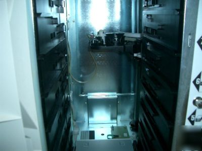
With the magazines removed, locate the picker assembly, pictured
below. It is located inside the unit, behind the magazine/drive bay area. It
travels up and down on two shafts: one is round and spiraled, and the
other is square. The shafts are mounted near the right hand, inside panel
6. Move the picker up or down by manually rotating the spiraled shaft.
Position the picker at or near magazine bay 4.
7. If there is a CD being held by the picker, as in the picture below,
release the CD by doing the following:
With your left hand, hold the CD lightly by the edges. With your
right hand, push the white tab feature (see below) away from
you. The picker releases the CD.
921-156-401-00 August 2000 Page - 56
9. Close and lock the front door.
10. Plug in the power cable and power up the unit.
11. If the original problem persists, contact your Reseller or Service
921-156-401-00 August 2000 Page - 57
QuikStor Library 72 & 162, 1-1
921-156-401-00 August 2000 Page - 58
921-156-401-00 August 2000 Page-59
Warranty and Service Agreement
Important Warranty and Service Agreement Notice:
To avoid unnecessary down-time should your BDT QuikStor 72 or 162 need
service, it is important to register your Warranty as soon as possible. Contact
your QuikStor 72 or 162 Reseller to register your warranty and discuss your
Service Agreement protection options. Be sure to have the Serial Number and
K# of the QuikStor 72 or 162 ready when you contact your Reseller.